Dust Collection Systems for Shop Dust & Woodworking
This duct construction guide combines various standards for industrial woodworking HVAC into a single reference.
Minimum Required Gauges for Galvanized Steel Spiral Lockseam Pipe and Fittings
Table 1
| Diameter | -2″ WG | -4″ WG | -6″ WG | -10″ WG | -15″ WG | |||||
|---|---|---|---|---|---|---|---|---|---|---|
| Spiral Pipe | Fittings | Spiral Pipe | Fittings | Spiral Pipe | Fittings | Spiral Pipe | Fittings | Spiral Pipe | Fittings | |
| 4″ | 22 ga. | 20 ga. | 22 ga. | 20 ga. | 22 ga. | 20 ga. | 22 ga. | 20 ga. | 22 ga. | 20 ga. |
| 6″ | 22 ga. | 20 ga. | 22 ga. | 20 ga. | 22 ga. | 20 ga. | 22 ga. | 20 ga. | 22 ga. | 20 ga. |
| 8″ | 22 ga. | 20 ga. | 22 ga. | 20 ga. | 22 ga. | 20 ga. | 22 ga. | 20 ga. | 22 ga. | 20 ga. |
| 10″ | 22 ga. | 20 ga. | 22 ga. | 20 ga. | 22 ga. | 20 ga. | 20 ga. | 18 ga. | 20 ga. | 18 ga. |
| 12″ | 22 ga. | 20 ga. | 22 ga. | 20 ga. | 20 ga. | 18 ga. | 20 ga. | 18 ga. | 18 ga. | 16 ga. |
| 14″ | 22 ga. | 20 ga. | 20 ga. | 18 ga. | 20 ga. | 18 ga. | 18 ga. | 16 ga. | 18 ga. | 16 ga. |
| 16″ | 22 ga. | 20 ga. | 20 ga. | 18 ga. | 18 ga. | 16 ga. | 18 ga. | 16 ga. | 16 ga. | 14 ga. |
| 18″ | 20 ga. | 18 ga. | 18 ga. | 16 ga. | 18 ga. | 16 ga. | 16 ga. | 14 ga. | 16 ga. | 14 ga. |
| 20″ | 20 ga. | 18 ga. | 18 ga. | 16 ga. | 18 ga. | 16 ga. | 16 ga. | 14 ga. | 16 ga. + A1 | 14 ga. |
| 22″ | 18 ga. | 16 ga. | 18 ga. | 16 ga. | 16 ga. | 14 ga. | 18 ga. + A1 | 14 ga. | 16 ga. + A1 | 14 ga. |
| 24″ | 18 ga. | 16 ga. | 16 ga. | 14 ga. | 16 ga. | 14 ga. | 18 ga. + A1 | 14 ga. | 16 ga. + A2 | 14 ga. |
A1 = min. 1″ x 1″ x 1/8″ angle ring reinforcing (12 foot maximum spacing) with 9 stitch welds 1.0″ long
A2 = min. 1″ x 1″ x 1/8″ angle ring reinforcing (12 foot maximum spacing) with 9 stitch welds 1.5″ long
Most engineers and contractors that work with educational facilities are familiar with standard HVAC design practices and SMACNA duct construction standards. There are many specialty duct systems that fall under lesser-known standards and criteria. The ducts used in vocational woodshop dust collection systems may outwardly appear to be the same spiral lock-seam duct and fittings used for HVAC applications. The static pressure ranges may fall within those found in the SMACNA HVAC Duct Construction Standards.
However, the actual requirements for a duct system in this application are higher and involve other standards. This Duct Construction Guide combines those various requirements into a single reference. This guide is not intended to cover commercial and industrial woodworking facilities. It lists the references used here, and most have greatly expanded ranges of size and capacity that can be used for those applications. The scope of this guide is as follows:
- Vocational woodworking shops in secondary and technical education facilities
- Duct systems operating at -15” WG and less
- Duct systems 24” diameter and smaller
- Systems in operation less than 1,000 hours per year
- Galvanized steel or black iron
Dust collection ductwork may be fabricated to a more robust standard than typical HVAC duct, but the cost does not have to be egregiously higher. The products and methods we recommend are chosen to meet the requirements in the most cost-effective way. Dust collection ducts are recommended to be round in shape. Rectangular and flat oval ducts would require heavier metal gauges and extensive reinforcement They also have less efficient airflows and corners where particulate can be trapped. Traditional round “blowpipe” systems could be used, utilizing longitudinal seam construction. A system using spiral lock-seam construction will typically use lighter thickness materials, with diameter/thickness ratios of as much as 1800. Greater stiffness is inherent in their construction.
Most vocational woodworking shop dust collectors operate in the range of -6 to -15” WG. For the relatively small diameters, the gauges are sufficient to avoid collapse. The particulate transported –– sawdust and small wood chips –– does not cause much impact damage or abrasion. Frankly, one of our greatest concerns we try to prevent is unintentional damage caused by the users. More than once, we’ve been consulted on jobs where HVAC-grade duct was installed and subsequently damaged. It seems a popular method for breaking up debris clogs is to “whack the duct with a big stick” instead of utilizing the cleanouts or disassembling duct for cleaning. The fittings and any flange need to be fully-welded construction.
Most HVAC-grade fittings and assemblies use tack-welds, screws, or rivets that are then sealed with mastics. Mastics should not be used on the interior of sawdust collection systems. Wood chips and sawdust would become embedded in the mastic, causing a chronic clogging issue. For all of the above reasons, the minimum gauge used for a vocational woodworking shop dust collection system duct is 22 gauge. In addition to durability, that is also the lightest gauge that can be consistently welded in most production facilities.
Design and Layout
Dust collection systems are typically designed using the Constant Velocity method. Each item of shop equipment has a recommended flow rate of exhaust air — either provided by the manufacturer or taken from a reference such as the ACGIH “Industrial Ventilation” (see Table x).
Woodworking equipment generally pro-duces two types of debris. Sanders and band saws produce fine sawdust. Table saws, lathes, joiners and planers produce larger chips. Both types of debris have a Minimum Transport Velocity. That is the velocity that must be maintained from the shop equipment to the collector to avoid debris settling in the duct and potentially producing clogs. As ducts from different shop equipment merge into the trunk, the highest of the Minimum Transport Velocities must be maintained from that point to the collector.
Typical Woodshop Equipment
Table 2
| Source | Shop Equipment | Exahust Flow Rate, acfm | Min. Duct Velocity | ||
|---|---|---|---|---|---|
| VS-95-01 | Bandsaw | bottom | top | TOTAL | |
| Up to 2″ blade width | 350 | 350 | 700 | 3500 | |
| 2-3″ blade width | 350 | 550 | 900 | 3500 | |
| VS-95-02 | Floor Table Saw | base | guard | TOTAL | |
| Up to 16″ saw blade dia. | 545 | 100 | 645 | 4000 | |
| Over 16″ saw blade dia. | 785 | 100 | 885 | 4000 | |
| Saw with dado blade | 785 | 100 | 885 | 4000 | |
| VS-95-03 | Radial Arm Saw | bottom | top | TOTAL | |
| 430 | 70 | 500 | 4000 | ||
| VS-95-10 | Single Drum Sander | TOTAL | |||
| Drum surface up to 200 in2 | 350 | 3500 | |||
| 200 – 400 in2 | 550 | 3500 | |||
| 400 – 700 in2 | 790 | 3500 | |||
| VS-95-12a | Disc Sander | TOTAL | |||
| Disc diameter up to 12″ | 350 | 3500 | |||
| 12 – 18″ | 440 | 3500 | |||
| VS-95-13 | Horizontal Belt Sanders | head | tail | TOTAL | |
| Belt width up to 6″ | 440 | 350 | 790 | 3500 | |
| 6 – 9″ | 550 | 350 | 900 | 3500 | |
| 9 – 14″ | 800 | 440 | 1240 | 3500 | |
| VS-95-15 | Woodworking Lathe | TOTAL | |||
| 880 | 4000 | ||||
| VS-95-20 | Jointers | TOTAL | |||
| Knife length up to 6″ | 350 | 4000 | |||
| 6 – 12″ | 440 | 4000 | |||
| 12 – 20″ | 550 | 4000 | |||
| Table 13-95-1 | Single Planers or Surfacers | TOTAL | |||
| Knife length up to 20″ | 785 | 4000 | |||
| 20 – 26″ | 1000 | 4000 | |||
| 26 – 32″ | 1400 | 4000 | |||
| Table 13-95-1 | Double Planers or Surfacers | bottom | top | TOTAL | |
| Knife length up to 20″ | 550 | 785 | 1335 | 4000 | |
| 20 – 26″ | 785 | 1100 | 1885 | 4000 | |
| 26 – 32″ | 1100 | 1400 | 2500 | 4000 | |
| Table 13-95-1 | Floor Sweep | TOTAL | |||
| 6″ dia. | 800 | 4000 | |||
| 8″ dia. | 1400 | 4000 | |||
Woodworking shop dust collection systems are designed for all equipment hookups to be drawing their recommended exhaust flow rates at any time the system is operating. Even though a saw or sander may not be in use, shutting off the exhaust flow from it would cause a decrease in trunk flow between that equipment branch and the collector. Those sections would drop below the Minimum Transport Velocity and clogs would potentially form.
All of this makes sizing the ducts fairly easy. You know your cumulative exhaust flow rate (cubic feet per minute). You divide that by the prevailing Minimum Transport Velocity (feet per minute). The result is Square Feet of duct diameter. Simply round that down to the next available duct size. Table 3 below shows the available sizes of spiral lockseam duct from Spiral Pipe of Texas and their area.
Duct Sizes and Area
Table 3
| Typical Flow (cfm) | |||
|---|---|---|---|
| Dia. | Area (ft.2) | at 3500 FPM | at 4000 FPM |
| 3″Ø | 0.049 | 172 | 196 |
| 4″Ø | 0.087 | 305 | 349 |
| 5″Ø | 0.136 | 477 | 545 |
| 6″Ø | 0.196 | 687 | 785 |
| 7″Ø | 0.267 | 935 | 1069 |
| 8″Ø | 0.349 | 1222 | 1396 |
| 9″Ø | 0.442 | 1546 | 1767 |
| 10″Ø | 0.545 | 1909 | 2182 |
| 11″Ø | 0.66 | 2310 | 2640 |
| 12″Ø | 0.785 | 2749 | 3142 |
| 13″Ø | 0.922 | 3226 | 3687 |
| 14″Ø | 1.069 | 3742 | 4276 |
| 15″Ø | 1.227 | 4295 | 4909 |
| 16″Ø | 1.396 | 4887 | 5585 |
| 17″Ø | 1.576 | 5517 | 6305 |
| 18″Ø | 1.767 | 6185 | 7069 |
| 19″Ø | 1.969 | 6891 | 7876 |
| 20″Ø | 2.182 | 7636 | 8727 |
| 21″Ø | 2.405 | 8419 | 9621 |
| 22″Ø | 2.64 | 9239 | 10559 |
| 23″Ø | 2.885 | 10098 | 11541 |
| 24″Ø | 3.142 | 10996 | 12566 |
Energy efficiency is as important in dust collection as it is in any other type of ventilation. The need for Minimum Transport Velocities prevents design methods such as static regain from being used to reduce system pressure drop. Duct system layout, exhaust flow rate and the cumulative duct and fittings pressure losses dictate the system pressure – and the required fan horsepower. Creating an energy efficient system really comes down to designing the most efficient duct system layout – have the shortest possible distance between the shop equipment and the collector, and get there on the straightest line. It also helps to use efficient fittings, and we will go over them below.
Elbows
Elbows and bends should be a minimum of 2 gauges heavier that the straight ducts of the same size used in a system. Elbow centerline radii should be a minimum of 2.0 and 2.5 recommended. All 90-degree elbows to 6” diameter should be 5-piece, larger sizes to be 7-piece construction. Angles other than 90-degrees should have a proportional number of segments. However, prefabricated elbows of “smooth construction” can be used.
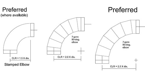
Diagram demonstrating ideal elbow radii measurements.
Where possible, we recommend the use of these die-formed elbows with a centerline radius of 1.5. The loss coefficients for these elbows are actually less than for segmented elbows with radii of 2.0 and 2.5, thus better efficiency at a lesser cost. They are only available in the smaller diameters. It should be noted that not all “die-stamped” or “pressed” elbows meet the minimum gauge requirements. Some are light as 25-gauge die-formed elbows for this type of system, and only where the system design pressure allows 20-gauge construction in that size.
Branch Fittings
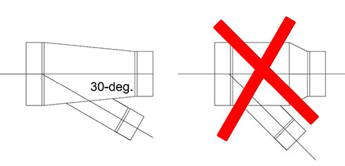
Woodshop dust collection systems use “tapered body” branch fittings. Most HVAC duct systems use “barrel” type fittings where the branch enters a constant-sized trunk. Any upstream reductions are made by putting a reducer on the upstream end. The problem with this type of fitting is that Minimum Transport Velocity is not maintained. Debris will settle out where both the tap and reducer meet the barrel, potentially causing clogs. Tapered body transitions are required and a maximum 30-degree branch angle is preferred. The length of the tapered body should be a minimum of 5 times the difference of the upstream and downstream diameters.
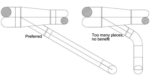
The branch fittings in the trunk duct should be located on the collector side from the woodshop equipment, on a straight line from the elbow turning vertically down to the equipment.
You should not try to effectively turn these branch fittings into 90-degree branches by combining a 30-degree lateral tap with a 60-degree elbow. This combination adds unnecessary field joints, additional pressure drops, plus an expensive elbow (60-degree elbows are not commonly available in die-stamped construction). The branch fittings in the trunk duct should be located on the collector side from the woodshop equipment, on a straight line from the elbow turning vertically down to the equipment.
Branch fittings entering the trunk directly opposite each other, “crosses”, should not be used. They created turbulence within the duct, leading to higher pressure drops and unpredictable transport velocity performance. If two items of shop equipment are located close to each other on opposite sides of the dust collector main. It is best to position them where their corresponding branch inlets, if extended across the profile of the main, do not overlap. The ideal design is more separation, the better.
The last branch in the system should be made with a capped lateral and the branch should be no more than 6” from the end. The removable end cap is used as a cleanout.
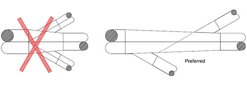
The ideal design is more separation, the better.
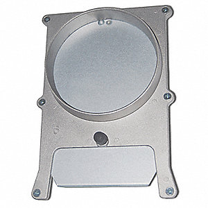
Blast Gates and Floor Sweeps
Most woodshop dust collection systems have manual blast gates at each piece of shop equipment. Simple aluminum cast body gates are not expensive and have a thumb-screw for locking them in place. They should be located in the vertical duct riser from the shop equipment, approximately 42” above the floor for ease of access, and 5 diameters away from the elbows.
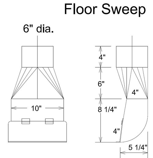
They are generally not used for balancing the system or shutting off unused equipment. They are most commonly used in conjunction with floor sweeps and shop cleanup. The exhaust flow rates of the floor sweeps are not usually included in the total system volume, this is a cost saving measure. A smaller system design flow means smaller duct and a smaller fan. When sweeping up the shop floor, you close the blast gates on the shop equipment, open the blast gates to your floor sweeps, then turn your dust collector on. You should do a separate system calculation to determine that your fan, with only floor sweeps open, can maintain the Minimum Transport Velocity for the cumulative floor sweeps of 4,000 FPM to avoid potential clogs.
Flexible Hoses
Flexible ducts are commonly used for final connection to shop equipment. This allows some movement and positioning of normally fixed equipment. Such flexible duct should be as short as possible (2-foot maximum length recommended) and have a minimum amount of bending. The flexible duct should be a no collapsible hose, related for the pressure, and for the intended use. Some equipment has a recommendation for a small diameter flexible hose of longer length to be used where the attached pickup point is not fixed (blade guards on table saws and traveling heads on radial arm saws). Length should be limited to the expected movement.
Duct Joint Assembly
A lot of money – and limitations – get added to shop dust collectors through the overuse of proprietary duct assembly systems. The idea of a system you can put together with external V-clamps sounds great. You can avoid putting obstructions into the airstream similarly to traditional screw-and-glue HVAC duct joints, but to get those nice rolled duct ends, you have to go to longitudinal seam duct. This limits your maximum lengths (shorter duct equals more joints to put together) and you end up with a lot of custom lengths or expandable lengths. We recommend a more practical –– and less expensive –– system of duct connectors.
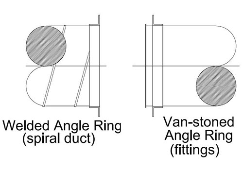
We recommend a more practical –– and less expensive –– system of duct connectors.
The main trunks of dust collection systems are relatively straight runs in predictable and fixed positions. Most of the cutting and adjusting happens in the smaller runouts to the shop equipment. Our recommendation is to fabricate the main trunk lines of 14” diameter and larger as cut-to-length spiral lock-seam pipe and fittings with flanged ends. Light gauge angle rings, such as the SPOT Flange, are sufficient for these applications and can be welded to spiral lock-seam pipe ends and van-stone to fittings ends. These flanges can be connected with self-tapping sheet metal screws because such screws will not penetrate the airstream. If a joint is designed for disassembly, pre-punched angle rings can be used, and flanges bolted together.
For ducts 12” diameter and smaller, we recommend using the MU Over collars from METU-System. These are a wide single tightening bolt. They are economical and make joint assembly fast. Best of all, you don’t have to pre-order all of your small diameter deducts cut-to-length. This is important when you are trying to make hard connections from your dust collector to shop equipment you may not even have yet.
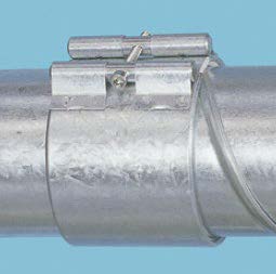
MU Over collars recommended for ducts less than 12" in diameter.
Some material handling duct systems require seams and joints to “lap in direction of airflow”. This is intended to reduce particulate buildup when transporting long fibers that could snag on exposed metal ends. They are not required or recommended by any of the references used in this guide for vocational woodshop dust collection systems. Proper spiral duct systems follow tolerance standards that minimize the gap between male-sized fitting and coupling ends and the female-sized ends of spiral ducts. The goal is a “friction fit”. You should have a slip fitting into a section of spiral duct.
Cleanouts
Cleanouts should be used in horizontal duct runs, near elbows, junctions, and vertical runs. They should be spaced a maximum 12 feet apart for ducts 12” diameter and smaller, and maximum 20 feet apart for larger diameters. For smaller diameter branches to equipment, the removal of a duct section with the use of the MU Over collars is an effective cleanout. For the larger primary trunk ducts, removing a section for cleanout is less desirable and practical.
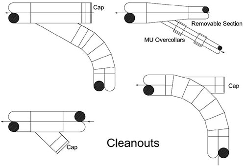
Cleanouts should be used in horizontal duct runs, near elbows, junctions, and vertical runs.
The most cost-effective method for producing a good cleanout is through the use of removable caps. We have already mentioned a removable cap for the last branch of the trunk ducts. Within straight sections of trunk ducts, lateral branches with removable caps can be added. For 90-degree directional changes in the trunks, removable caps can be utilized by having either heel-tapped elbows or using a lateral branch + elbow for the primary flow (for 12” and smaller). Recommended cap size is trunk diameter – 2” for branches from the main, up to a maximum 12” diameter cap size. Caps on the through-end of branch fittings should be the same diameter as the trunk duct. The removable caps are fixed in place with an MU Over collar, so they can be easily removed with a single bolt.
Leakage
The recommended maximum leakage for a dust collection system is 2%. As with any duct system, a substantial portion of the leakage occurs at the duct joints. In woodshop collection systems, the additional sources of leakage are the slide blast gates and cleanouts. The use of the gasketed MU Over collars will eliminate most leakage at joints and cleanouts. Other types of cleanouts such as split sleeves and hinged access doors have been commonly used. Once opened, they are notoriously difficult to keep sealed. Rectangular connections and openings should be avoided because of their tendency for corner leakage.
Suspension and Support
For suspension and support, the weight of dust collection duct is calculated as the weight of the duct itself, plus the weight of the sawdust filling half the duct. Table 4 has nominal design weights for Vocational Woodworking Shop Dust Collection Systems using spiral lock-seam duct. Ducts can be suspended using appropriately sized cable hangers, teardrops strap hangers, or saddles. Hangers should be located as close as possible to joints and elbows (2” recommended) and maximum 12 feet apart. Longer hanger spacing can be used if the duct joints are flanged and guidelines found in the SMACNA Round Industrial Duct Construction Standards are followed (Sections 4.10 and 5.8). Duct systems covered in this guide are not intended to be walked on, so the 250-pound maintenance load can be omitted.
References
- Industrial Ventilation — A Manual of Recom-mended Practice for Design (30th Edition – 2019) — ACGIH
- Round Industrial Duct Construction Standards (2nd Edition – 1999) — SMACNA
- NFPA 91 – Standard for Exhaust Systems for Air Conveying of Vapors, Gases, Mists, and Particulate Solids – 2020 — NFPA
- Chapter 19 “Duct Construction” — 2016 HVAC Systems and Equipment Handbook — ASHRAE
- Chapter 21 “Duct Design” — 2017 Fundamen-tals Handbook — ASHRAE
- Chapter 8 “Educational Facilities” — 2019 HVAC Applications Handbook — ASHRAE
- Chapter 33 “Industrial Local Exhaust Systems” — 2019 HVAC Applications Handbook — ASHRAE
Spiral Duct Weights
Table 4
| Duct Weights (per lineal foot) | |||||||||
|---|---|---|---|---|---|---|---|---|---|
| 22 gauge | 20 gauge | 18 gauge | 16 gauge | ||||||
| Dia. | Area (ft.2) | Duct Only | Duct + Particulate | Duct Only | Duct + Particulate | Duct Only | Duct + Particulate | Duct Only | Duct + Particulate |
| 3″Ø | 0.049 | 1.3 | 1.62 | 1.5 | 1.82 | 1.9 | 2.22 | ||
| 4″Ø | 0.087 | 1.7 | 2.27 | 2 | 2.57 | 2.6 | 3.17 | ||
| 5″Ø | 0.136 | 2.1 | 2.99 | 2.5 | 3.39 | 3.2 | 4.09 | ||
| 6″Ø | 0.196 | 2.5 | 3.78 | 2.9 | 4.18 | 3.8 | 5.08 | 4.7 | 5.98 |
| 7″Ø | 0.267 | 2.9 | 4.64 | 3.4 | 5.14 | 4.5 | 6.24 | 5.5 | 7.24 |
| 8″Ø | 0.349 | 3.3 | 5.57 | 3.9 | 6.17 | 5.1 | 7.37 | 6.3 | 8.57 |
| 9″Ø | 0.442 | 3.8 | 6.67 | 4.4 | 7.27 | 5.7 | 8.57 | 7 | 9.87 |
| 10″Ø | 0.545 | 4.2 | 7.75 | 4.9 | 8.45 | 6.4 | 9.95 | 7.8 | 11.35 |
| 11″Ø | 0.66 | 4.6 | 8.89 | 5.4 | 9.69 | 7 | 11.29 | 8.6 | 12.89 |
| 12″Ø | 0.785 | 5 | 10.11 | 5.9 | 11.01 | 7.7 | 12.81 | 9.4 | 14.51 |
| 13″Ø | 0.922 | 5.4 | 11.39 | 6.4 | 12.39 | 8.3 | 14.29 | 10.2 | 16.19 |
| 14″Ø | 1.069 | 5.8 | 12.75 | 6.9 | 13.85 | 8.9 | 15.85 | 11 | 17.95 |
| 15″Ø | 1.227 | 6.3 | 14.28 | 7.4 | 15.38 | 9.6 | 17.58 | 11.7 | 19.68 |
| 16″Ø | 1.396 | 6.7 | 15.78 | 7.9 | 16.98 | 10.2 | 19.28 | 12.6 | 21.68 |
| 17″Ø | 1.576 | 7.1 | 17.35 | 8.3 | 18.55 | 10.8 | 21.05 | 13.3 | 23.55 |
| 18″Ø | 1.767 | 7.5 | 18.99 | 8.8 | 20.29 | 11.6 | 23.09 | 14.1 | 25.59 |
| 19″Ø | 1.969 | 7.9 | 20.7 | 9.3 | 22.1 | 12.1 | 24.9 | 14.9 | 27.7 |
| 20″Ø | 2.182 | 8.3 | 22.48 | 9.8 | 23.98 | 12.8 | 26.98 | 15.6 | 29.78 |
| 21″Ø | 2.405 | 8.8 | 24.43 | 10.3 | 25.93 | 13.4 | 29.03 | 16.4 | 32.03 |
| 22″Ø | 2.64 | 9.2 | 26.36 | 10.8 | 27.96 | 14 | 31.16 | 17.2 | 34.36 |
| 23″Ø | 2.885 | 9.6 | 28.35 | 11.3 | 30.05 | 14.7 | 33.45 | 18 | 36.75 |
| 24″Ø | 3.142 | 10 | 30.42 | 11.8 | 32.22 | 15.3 | 35.72 | 18.8 | 39.22 |
This construction guide is a compilation of information contained in the above referenced guides and standards, and all performance claims are per those standards.
Browse OurDuct Solutions
Spiral Pipe of Texas (SPOT) fabricates high quality, MADE IN THE USA sheet metal products for the heating, air conditioning and ventilation (HVAC) industries.

